Quantcast
Channel: Michele's GNSS blog
Viewing all 37 articles
Browse latest View live

Low cost RTK performance round-up

$
0
0

Having done quite a bit work since the first Yuan10 was built, I think it's time to write a small summary.

I recently put up a navXperience 3G+C antenna that will serve as reference for all future RTK work in this area. With the support of the reference station University of Pisa and their reference observations at 0.2Hz I run RTKLIB (RTKNAVI and RTKPOST) for several days using several low-cost receivers that I assembled.
This should be somehow considered the best possible scenario, having a short 1.5Km baseline.. nevertheless the results are quite exciting I believe.


Figure 1: Yuan10: Skytraq S1315F-RAW


The plots above show solving of the integer ambiguities in about 5 minutes and reaching an accuracy of about 4cm square.

Figure 2: Rappen10 mMCX version: uBlox NEO-6P (RTK mode)


Again, the NEO-6P brings the position down to 4cm square accuracy in less than 10 minutes.

Figure 3: Denga10: NVS NV08C-CSM


The NV08C-CSM solves the carrier phase integer ambiguities and also brings down the accuracy to about 4cm square.

Each of these receivers has his specialty:
  • the S1315F-RAW has 20Hz raw measurements update rate, which is still unmatched performance by other low-cost receivers
  • the uBlox NEO-6P has integrated PPP for high accuracy standalone mode, no other low-cost receivers claims that
  • the NVS NV08C-CSM has Glonass!
Cheers,
Michele

P.S.: I attached a trimmed version of the data used to obtain these results here. Please note how the NVS observations are covered by NDA and therefore not included.

P.P.S.: The latest FW from NVS (dated 27 Feb 2012) improves dramatically the quality of the NV08C-CSM raw measurements: results above are not representative anymore.


Spring news in the GNSS and SDR domain

$
0
0
I have been following in the last few days interesting developments in the GNSS and SDR domain.

1. NV08C-CSM and dual constellation RAW measurements

It's recent news that NVS has lifted the constraints on the firmware with RAW data for GPS and Glonass on L1. In my opinion this is one of those rare times that the rules of the game are changed by one of its players.
Essentially the NV08C-CSM provides real-time kinematic capability at 10Hz, with a price point as low as 35EUR/piece in small quantities. It is already possible to download an unofficial version of RTKNavi.exe and RTKConv.exe here, but RTKLIB will officially support the receiver from next version anyway.
Below are some pics of what Denga10 and the navXperience 3G+C could do with the good old 2.4.1 "Static Precise Point Positioning" over three hours.. bringing down the error to less than 20cm in complete standalone mode (by using only broadcast products).

Rtknavi (NVS mod) doing static PPP with 14 sats

Rtknavi (NVS mod) available satellite close-up

Glonass broadcast navigation data

GPS broadcast navigation data

GPS/Glonass observations.. 21!

Satellites used in the fix

From cold start, first three hours, ground track
From cold start, first three hours, position


From cold start, third hour, ground track

From cold start, third hour, position


The likes of Novatel, Trimble, Hemisphere, etc are not going to like it I suppose. On the other hand, users have perhaps a cheaper option to enter the high-precision domain.

2. RTL-SDR

For once, the group of innovators is European.
These guys of osmocom are smart and -what's even better- their work with the open source team. RTL-SDR is, I believe, one of the freshest finds in the Software Defined Radio domain. The Fun Cube Dongle, developed in UK, is already a very clever tool. But finding the super-tuner Elonics E4000 (note, again a UK Company) in 25$ USB DVB-T dongles and being able to grab data in a 3MHz bandwidth between 64MHz and 1.7GHz... that is really cool.

I had to buy one! ...actually two before I found the E4000..
A Terratec Cinergy T Stick Black rev.1, with the FC0012 which is not suitable for GPS
A Newsky TV28T, with the E4000.

The Realtek RTL2832U demodulator uses a 28.8MHz crystal by default.. which has too poor accuracy for a GPS receiver.. but a SDR acquisition algorithm can easily handle 100+kHz of apparent Doppler shift in the frequency search :)
So for a nominal sky plot as the one below:


And a signal looking like as follows:

Power spectrum around GPS L1, FS=2.728MHz
The ADC is saturated.. the gain I set was too high.

I could acquire the following birds:

SV 9: Doppler +112000.0 CodeShift:     99 xcorr: 553566.6
SV12: Doppler +113500.0 CodeShift:    502 xcorr: 301126.3
SV15: Doppler +110000.0 CodeShift:   1847 xcorr: 871305.9
SV17: Doppler +110500.0 CodeShift:   2225 xcorr: 401100.6
SV18: Doppler +110000.0 CodeShift:     38 xcorr: 368766.1
SV26: Doppler +107000.0 CodeShift:   1779 xcorr: 511844.4
SV27: Doppler +110500.0 CodeShift:    264 xcorr: 650033.9
SV28: Doppler +107500.0 CodeShift:    203 xcorr: 320405.6


The next step is to have my new version of GPS-SDR processing the data in real-time.. won't be long!
I managed to upload the binary file which is long enough for everyone with a SDR receiver to calculate the position. I used FS=2.048MHz and a nominal IF of 0.0Hz (but because of the crystal inaccuracy the IF actually falls at about 110kHz). The data type is I&Q interleaved int8_t.

https://rapidshare.com/files/558977948/20120415_1714BST_fs2048_iq8.001.dat
https://rapidshare.com/files/2431212520/20120415_1714BST_fs2048_iq8.002.dat
https://rapidshare.com/files/4187716662/20120415_1714BST_fs2048_iq8.003.dat
https://rapidshare.com/files/107864226/20120415_1714BST_fs2048_iq8.004.dat

3. Open source FPGA receivers

I waited too long for the code from the University of Tampere: they were promising to licence the TUTGNSS and never happened.
Finally the Open Source community is bringing to the reality an Open Source FPGA implementation of a GPS receiver based on the Namuru / Zarlink GP2021 correlator structure and soft CPU cores (the LatticeMico32 Milkymist and the Altera NiosIIe). As also scientists at the University of Tokio (remember RTKLIB?) are involved, this time I know it is going to happen.
Some useful links:
http://gnss-sdr.ru/index.php?blogid=2
http://en.qi-hardware.com/wiki/GPS_Free_Stack
http://blog.goo.ne.jp/osqzss/

Stay tuned, GNSS is evolving rapidly!

The GPS tracker to beat (smallest, lightest, and most durable)

$
0
0
Figure 0: Please read below.
From the very early days of GPS snapshot technology has been proposed as a way of reducing power consumption and footprint of a radio positioning device. Some papers about NASA microGPS date back to late ‘90ies:

Later on many Companies tried to patent this technology and bring it to the market. Most of them have been acquired or have merged - see the latest acquisition of CSR “mobile business” (whatever that means!) from Samsung.
To our knowledge until today all development efforts led to products with disputable market readiness, if otherwise mostly devoted to picture geo-tagging.
Instead, the assumption that a snapshot approach could beat (from the cost and power consumption point of view) a hardware baseband has always been contradicted by Moore’s law and market demand. Lead manufacturers now release complete GPS engines on a chip smaller than what was before the RF Front-End part only. Compare e.g. the CSR GSD4e (3.5 x 3.2 x 0.6mm 42-ball WLCSP) and the Skyworks SE4150L (4 x 4 x 0.9 mm 24-pin QFN). That is probably why the complexity associated to a snapshot positioning approach has never won over a slightly more expensive and power consuming standard GPS receiver.
Probably the real value of a snapshot approach has not been identified yet and in our opinion is to be searched in other domains such as geoencryption and GNSS authentication:

So we longed for a Company that would own the technological skills to provide a new standard in terms of snapshot positioning. 
Cellguide has been in the business several years now but only recently released a real hardware module – simple to use and available for sale – that works with a snapshot positioning approach and has specifications that could dramatically change the tracking business: the Robin.

We bought an evaluation kit (expensive, but breaks the ice) and we are testing it together with other 
enthusiastic engineers. 

A Robin device on its cradle (used for charging, programming, and downloading the snapshots on the PC) looks like this:

Figure 1: Robin device on its cradle
 A couple of Robin devices next to each other:

Figure 2: Two robin devices next to each other


The Robin brochure says already a lot, but I wanted to show the results of a real test (on the beach – it is summer after all).
The reference path was roughly this one:

Figure 3: Approximate reference path
The little wire antenna in the pictures above was used (which is terrible compared to a patch antenna of course). 
Please note that each snapshot is - by design - completely independent from the others.

64ms snapshots (at 1Hz) lead to the following positioning results:

Figure 4a: 64ms snapshots, raw
Figure 4b: 64ms snapshots at 1Hz, Kalman filtered
Figure 4c: 64ms snapshots at 0.2Hz, Kalman filtered
The same was test was also reproduced by taking 512ms snapshots (higher sensitivity) at 1Hz.

Figure 5a: 512ms snapshots at 1Hz, raw
Figure 5b: 512ms snapshots at 1Hz, Kalman filtered
Figure 5c: 512ms snapshots at 0.2Hz, Kalman filtered
 Results can be summarised in the following:

Figure 6a: 64ms snapshots, raw (red) and filtered (green)
Figure 6b: 512ms snapshots, raw (red) and filtered (green)
Figure 6c: filtered output for 64ms (diamonds) and 512 (circles)

Robin was born at Cellguide for wildlife tracking but as we came across it we could not help thinking it shall be employed in lots of other cases as well. The Aclys chip (earth of Robin) has a low data rate, low pin count SPI bus compatible even with simple 16bit micro-controllers. It can therefore be embedded in very small and cost effective devices to enable tracking capability where it was not possible before.
We see potential in this technique and we hope you enjoyed reading as as much as we did running the tests!

Greetings,
Michele

P.S.: For further information please contact directly the Cell-guide guys at info@cell-guide.com

Full Galileo IOV

$
0
0
After a long wait, it was a pleasure this morning to record the full IOV constellation.

Figure 1: Orbitron prediction of Galileo visibility this morning.
The NV08C-CSM receiver with a R&D firmware could track all 4 IOV Galileo satellites, as well as another 21 SVs between GPS, Glonass, and EGNOS.

Figure 2: NVS Storegis recording NMEA with all 4 IOV satellites.
An excerpt of the log file:

$GPGGA,071500.00,4342.8439,N,01024.2096,E,1,18,00.6,023.3,M,47.9,M,,*55
$GPRMC,071500.00,A,4342.8439,N,01024.2096,E,00.00,206.5,141212,,,A*54
$GPGSV,4,1,13,03,21,287,44,06,41,290,48,16,50,307,49,18,33,136,44*71
$GPGSV,4,2,13,21,72,066,47,22,12,170,39,29,24,084,42,30,73,245,51*70
$GPGSV,4,3,13,31,16,210,44,33,33,215,42,37,38,164,37,39,37,159,40*75
$GPGSV,4,4,13,40,23,124,36*4C
$GLGSV,3,1,09,68,05,014,34,69,31,060,42,70,26,122,44,74,07,190,40*60
$GLGSV,3,2,09,75,42,233,44,76,36,310,46,84,30,060,37,85,62,355,46*6A
$GLGSV,3,3,09,86,31,283,47*5A
$GAGSV,1,1,04,161,00,000,41,162,00,000,47,169,00,000,42,170,00,000,43*60
$GNGSA,A,3,22,03,06,30,16,18,21,29,31,,,,01.1,00.6,01.0*19
$GNGSA,A,3,70,86,76,75,69,84,85,68,74,,,,01.1,00.6,01.0*12
$PORZD,A,001.1*3C
$GNGBS,071500.00,0.9,0.6,2.3,,,,*52


I also turned on my SdrNav00 modified with a 26MHz oscillator and obtained the following:
Figure 3: SdrNav00 signal properties.
Figure 4: SdrNav00 signal power spectrum

Figure 5: Galileo acquisiton on E1b signal.

Galileo pseudoranges were logged by NV08C-CSM and by my SdrNav00, so the next step is to try PVT with the TUM orbits.


Fruit-Bat Tracking with Robin GPS Logger

$
0
0
I have recently received the results of an interesting experiment done with Robin, Cellguide's snapshot GPS tracker so I thought I should share it with the Community.

Figure 1: Yes, a fruit bat
Becuase of its size and weight Robin enables new applications of GPS technology, including wildlife tracking of course. Particularly of species on which was very difficult in the past.


Test Setup 
  • CellGuide Robin GPS Logger with 100mAh battery (2.2 grams): total weight 4.75 grams
  • Programmed to operate every day between 5pm to 5am
  • Total length of the experiment: 72 hours
  • Operating regime:
    • Fix every 3 seconds
    • Medium sensitivity (GPS snapshot length of 128ms)
The test was conducted by researches from Tel Aviv University. They packed Robin in a light weight plastic wrap along with a UHF beacon device, and attached everything to the bat using a special medical glue that only sticks for a few days.

Figure 2: A picture of the fruit bat with Robin on the back.
Figure 3: The test area.
During the first night, the bat visited three other trees along its path. On the second night, the bat took a bit of a different path but still quite similar to the one from the previous night and flew to the same tree. Then, pretty much as the two previous nights, the bat flew to his favorite tree again.


 Figure 4: From left to right: first, second, and third night

The Robin logger was found two weeks later inside the cave, using a UHF beacon device. A summary of the experiment is given below.

Figure 5: All nights on the same map.
Despite this experiment being simply very cool for a GPS passionate as I am, I shall probably mention here that I don't work for Cell-guide so for further information on the Robin GPS Logger please do contact the experts!
info@cell-guide.com

Cheers,
Michele

Wrapping up 2013 GNSS facts

$
0
0
Well, it has indeed been quite a long time since I wrote here the last time.
My personal situation has changed in such a way that it is hard to find the time to share my views and to comment your feedback on current advances in the GNSS R&D domain.
However I feel like dropping here an "end of the year" summary which serves more as a memorandum to me that anything else.
I might be challenging this article
http://gpsworld.com/2013-a-positive-year-for-location-industry/
but 2013 has not been a very good year for GNSS.
At least someone generally agrees:
http://qz.com/161443/2013-was-a-lost-year-for-tech/#!

Mass market receivers for low cost RTK
Lately there was one more item on the acquisitions list:
The above shows how aggressive this market is and leaves just a few players on the field.
Some of them, such as Intel, Qualcomm and Broadcom don't really sell to private and just target device manufacturers. Others have shelves as well and those are the most interesting for people thinkering with GNSS of course.
In no particular order:

Mediatek
Early in 2013 Mediatek announced MTK3333. This powerful true dual constellation receiver can be found in many modules (for example by Locosys and GlobalTop. Although impressive, it does not seem to offer pseudoranges or carrier phase at the moment.

uBlox
IMHO, uBlox has a confusing roadmap with 6th generation modules overlapping with 7th generation and now apparently 8th generation. I design with uBlox modules and it is a little awkward to tell my customers that modules already advertised for are due for release in 6 months. The Company has done an aggressive marketing of a "PPP" technology that has nothing to do with Precise Point Positioning, but rather with carrier phase smoothing. uBlox still manages to sell navigation modules which are not true dual constellation but either one or the other constellation. Their "P" and "T" modules have well established pseudorange, carrier phase and more measurements for GPS.

ST-Microelectronics
STM has released in 2013 the TeseoII true dual constellation IC. The STA8088FG is 7x7 mm and is very capable. Pseudoranges can be obtained with some firmware, but never carrier phase. Carrier phase is rumored to be available in Teseo3, which is to be released next year. STM is more open to Galileo than any other Company, but it is weird to find their GNSS products under "Automotive Infotainment and Telematics" category.. not that STM website is an easy one to navigate anyway.

NVS
NVS continued to innovate in 2013 by releasing new FW for their NV08C-CSM and -MCM modules. However, after the press release of compatibility with the popular precision navigation software RTKLIB, they went quiet. By the way, I wrote the support driver for their receiver into RTKLIB but never received a mention.. you are welcome. Next year NVS will release a new hardware revision of their modules, but nothing is told about changes to expect against the current. I have high expectations :)

Geostar Navigation
This Company was pretty new to me and came as a surprise in 2013. It offers a true dual GPS+Glonass receiver module. In my opinion has still to improve in terms of reliability but the preconditions are all good (website is updated often so at least the Company seems well up and running). Rumors want Geostar-Navigation to release a pseudorange and carrier phase capable firmware (for GPS at least) very soon.

Furuno
Furuno came back in 2013 with a true dual constellation chipset called eRideOPUS 7 and module called GN-87F. The Company has expressed interest in releasing Galileo compliant firmware soon and the chip seems to be able to output pseudoranges, but not carrier phase.

CSR
CSR has finally delivered a new standalone receiver IC, the SiRFstarV 5e. I bought the Telit Jupiter SE868 V2 (quite a mouthful) evaluation kit from Rutronik. I still did not have a chance of testing it out in real environment but it does track simultaneously GPS, SBAS and Glonass. The chip seems to be very swift and surely has best in class power consumption, but SiRF already departed from raw measurements path with their 3rd generation so I would not expect them to be back on that track now.

Skytraq
Last but not least, Skytraq was among the first ones to release a true dual constellation chip and module with the intention of supporting raw measurements. I bought some S4554GNS-LP back in 2011 already. Since then the Company has made a great progress in integration and quality of modules. The latest generation, the Venus8, has GPS 50Hz measurements, or GPS+Glonass at 20Hz. As all new modules comply with the uBlox NEO format, I already had a chance of integrating some S1216F8, S1216F8-GL and S1216F8-BD. Whilst not tested in the field but "only" with an Agilent GNSS simulator, these modules represent for me the greatest promise for 2014.
All GNSS enthusiastics should check out the NavSpark:
http://igg.me/p/603168/x/5902022
Although I am not a crowdfunding enthusiastic (see later as well) the news is that it is possible to get at least an evaluation kit (with libraries) for this powerful baseband processor for USD 199. There is a lot of room to play for sure, and 50Hz GPS raw measurements for less than USD 20 a module will buzz for sure.

  GNSS Software Defined Radios

Looking out for interesting devices to use for GNSS SDR, this year has been a promising one. But not all promises are kept, as I will explain below.

Memoto Camera

One year ago already, following the hype of the Cell-guide snapshot GPS technology, I decided for the first time to back a kickstarters project: the Memoto camera. This "lifelogging device" has an Aclys chip inside which will only turn on for a few milliseconds every so often and record a GPS signal snapshot, in order to achieve the lowest possible battery life. After more than 1 year not only I did not received the camera but my contact has been lost in the transition from Memoto to Narrative. Being my support request unanswered, it is hard to know wheter I have lost my pledge or not... fingers crossed.

Jawbreaker -> HackRF One

Michael Ossmann, creator of the Ubertooth, started developing other interesting devices for low cost SDR. I missed by very little the Jawbreaker giveaway back in June, so I decided to support its Kickstarters campaign for HackRF One, which is essentially the same object but not free and with 8 months more on its shoulders. Whether this time has actually served to real innovation or just made Michael more popular (at least well deserved in his case) and rich.
My plans of using HackRF One for GNSS record and playback are a little pushed back by the fact that it is a half-duplex design, although I see some potential by properly hopping between TX and RX.If and when I receive the thing.

Nuand BladeRF

BladeRF was probably the greatest disappointment so far. It mounts
  • the Lime Microsystems LMS6002D, a fully programmable RF transceiver capable of full-duplex communication between 300MHz and 3.8GHz
  • an Altera Cyclone 4 with options at 40KLE or 115KLE
  • a Cypress FX3 microcontroller
Sounds like the perfect board to have a GNSS receiver on FPGA, and a real-time continuous-time record and playback device. I received the boards back in Summer and was never really able to have them working reliably. I installed the Ubuntu several times, until now 13.10 seems to have native support at least for the libusb version they link to. Things might change tomorrow, but it has been six months of bleeding so far. Essentially the software is not stable. BladeRF might even work as a 450 USD spectrum analyzer once you install a leviathan like Gnuradio. But it won't work for me if it misses packets once in a while, if it randomly switches the I and Q channel, if it cannot tune to 1.5GHz in TX mode, if it works only with Renesas and NEC USB 3.0 hosts.

SwiftNav Piksi

Two bright guys, Fergus Noble and Colin Beighley founded Swiftnav and started developing Piksi, an "open source" GPS receiver for RTK implemented as a combination of a Spartan6 9KLE FPGA and STM32F4 168 MHz Cortex-M4 MCU. Swiftnav "kickstarted"Piksi back in the Summer, when I already had a sample of it. Unfortunately once the campaign was funded (and I was one of the backers of course) there has been little development on the software side. Sure, more boards were manufactured to address sales but Swiftnav customers are not yet able to see how the RTK engine will look like, nor they have visibility of the FPGA correlators code.
Actually those two are two valuable pieces of software so I cannot hide my sceptictism in believing the promised Open Source nature of the venture.
Before I publish here anything about Piksi, I need to be provided a simple way of
  1. recording data with the board connected to a perfect antenna. 
  2. converting the recorded stream into Rinex OBS
IMHO, those two are the fundamentals when a Company plans to sell a RTK capable receiver. It does not have to be small, to be low power, to have an embedded antenna if carrier phase isn't rock solid to begin with.
Very recently Swiftnav published a video (filmed in August, so why now?) where they show differential accuracy on the rooftop of their office building.. but that seems a very poor reward for three months of Github silence (1) (2).
I sent Fergus and Colin two pieces of the most recent Rap10LogWi release


asking them to try their RTK engine (I used their same MCU) on a bullet-proof low cost GPS receiver as the uBlox NEO6T.
I have not received any feedback so far.. I know they are busy investing their reward, but I think their customers (and I) need a bit of delivery of credibility at this point.
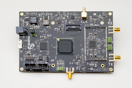
Ettus USRP B2x0

Probably the savior of my 2013 SDR hopes, the B2x0 boards from Ettus tick many boxes. They are a little expensive maybe, but they are supported by the UHD driver which has a huge community behind. How did Ettus manage to pull off a deal with Analog Devices and integrate first the super powerful AD9361 I don't know. The TI AFE7070 came close sometime this year in terms of chip integration, and the above mentioned LMS6002D (with its awkward footprint) even closer, but that ADI chip seems unbeatable right now. The Spartan 6 75KLE seems also large enough to run several channels of a GNSS receiver already. I will have access to a couple of these boards very soon and I cannot wait.

...TBC


R820T with 28.8 MHz TCXO

$
0
0
I recently looked around for tools to use as low cost spectrum scanners, being the objective frequency range 400 MHz to 1.7 GHz (incidentally, DVB-T and GPS).
Of course rtl-sdr is an attractive option so I dusted off some dongles I had bought 6 months ago in China and played again with them, coming to the conclusion that I really like it especially after its main limitation is overcome :)

The 28.8 MHz crystal is quite poor. I asked Takuji for a TCXO but he said he emptied his stock rapidly. Of course a replacement is nowhere to be found on the big distribution (Digikey, Mouser, Farnell, RS, etc..), so I went to an old time acquaintance at Golledge and, despite having to order 100 pieces, my request was fulfilled. After all, dongles look quite good with the new crystal:
Figure 1: RTL-SDR with 28.8 MHz TCXO (Golledge GTXO-92)

I measured the frequency deviation with my simple GPS software receiver and I happy to report that it is within spec, bounded to 2ppm. By the way, I tried using other GNSS software receivers and will write about my experience in another post soon.

On the frequency plan side, the R820T combined with the RTL2832U is great for GPS. Most people would use it with an active antenna, where the LNA solves the problem of losses due to the impedance mismatch (50 against 75 ohm) and the noise figure of the tuner (3.5 dB according to datasheet).
The frequency plan with an IF of 3.57 MHz solves elegantly the problem of LO feedthrough and I/Q unbalance typical of ZIF tuner. The IF is recovered automatically in the digital domain by the demodulator so it does not appear in the recorded file. 8bit I/Q recording at 2.048 Msps is more than sufficient for GPS and I also tracked Galileo E1B/C with it (despite some obvious power loss due to the narrow filter band). In my tests, I used a Dafang technology DF5225 survey antenna and the signal time plot shows that 5 bits are actually exercised. I powered the antenna with 3.3V from a Skytraq Venus8 (Ducat10 with S1216F8) through an all-by-one DC blocked passive 4-way splitter/combiner (6 dB unavoidable loss) from ETL-systems.

Figure 2, 3 and 4: Power spectrum, histogram, and time series at L1.

I posted three GPS files here:
https://app.box.com/s/wxizs3p7zu8x2jmbnzod
https://app.box.com/s/xvfabkqfkmehg5osa3ra
https://app.box.com/s/dqrel15mwj73xijflkma

Since someone asked for it, here are the tracking results of Galileo E19 plotted after the fact with Matlab:


and Galileo E20:


More to come later,
Michele

GNSS carrier phase, RTLSDR, and fractional PLLs (the necessary evil)

$
0
0
A mandatory principle when processing GNSS -in order to have high accuracy carrier phase- is to have a well defined frequency planning. This entails knowing precisely how the Local Oscillator (LO) frequency is generated.
With RTL-SDR it is not a trivial task given that both R820T and RTL2832U use fractional Phase Locked Loops (PLLs) in order to derive respectively the high-side mixing frequency and the Digital Down Conversion (DDC) carrier.
I guess most people use RTL-SDR with a 50ppm crystal so the kind of inaccuracies I am going to describe are buried under the crystal inaccuracy ..within reason.

Let us start from the common call

> rtl_sdr -f 1575420000

This means "set to 1575.42 MHz" but what is hidden is:
1) R820T, set to 1575.42e6 + your IF
2) RTL2832U, downconvert the R820T IF to baseband
.. there are approximations everywhere.

Now, the R820T has a 16 bit fractional PLL register meaning that it can only set to frequencies multiple of 439.45 Hz (exactly).
Instead, the RTL2832U has a 22 bit fractional PLL register meaning that is can recover IFs in steps of 6.8665 Hz (exactly).
Of course, nor 1575.42e6, nor 3.57e6 are exact multiples of either frequency so one always ends up with a mismatch between what he/she thinks he has set, and what really ends up with. Most of the times, this is fine. For GNSS it is not since carrier is accumulated over long intervals and even a few tenths of Hz will make it diverge from the truth.
So I went down the route of characterising the necessary evil of fractional PLLs.

The first test I did was to set the tuner to 1575421875, which leads to a -1875 Hz center frequency but is nicely represented in 16 bits using a 28.8 MHz reference (remember the R820T). In fact, 54 + 0.7021484375 = 54 + [1011001111000000]/2^16. ..ok well actually it fits on 10 :)

Here I found a small bug in the driver  and replaced the following messy (IMHO) code: 

/* sdm calculator */
while (vco_fra > 1) {
    if (vco_fra > (2 * pll_ref_khz / n_sdm)) {
        sdm = sdm + 32768 / (n_sdm / 2);
        vco_fra = vco_fra - 2 * pll_ref_khz / n_sdm;
        if (n_sdm >= 0x8000)
            break;
    }
    n_sdm <<= 1;
}


with 

mysdm = (((vco_freq<<16)+pll_ref)/(2*pll_ref)) & 0xFFFF;

Then I modified the IF of the R820T from 3.57 MHz to 3.6 MHz, as it is only a few kHz away and it is nicely represented on 16 bit  ..ok well it actually fits in 3 :)
Modifying the IF also impacted the RTL2832U fractional register of course.
I still had a significant error (about 115 Hz) which I could measure comparing the scaled code rate and the carrier rate (which should be proportional of a factor 1540).
After a long time wondering what could be happening, I decided to start tweaking the bits of the R820T.
One in particular called PLL dithering seemed suspicious. Disabling it kind of doubled the error to about 220Hz. Sad.. but I did recall now the resolution of the tuner (439.45 Hz) and guessed that there is a hidden 17th bit which toggles randomly when "dithering" and is instead fixed to 1 when "not dithering". A couple of references which could explain why are here:
http://petrified.ucsd.edu/~ispg-adm/pubs/KWangDissertation.pdf
http://www.ece.rochester.edu/users/friedman/papers/ISCAS_04_PLL.pdf

How sneaky! But I could nicely recover that 17th bit with the RTL2832U (which has 22).
So I have now rock-solid code-carrier assistance ^_^
Figure 1: Code-carrier mismatch when tracking a satellite with RTL-SDR
One step closer to integer ambiguity resolution?

Cheers,
Mic

Galileo RTK with NV08C-CSM hw 4.1

$
0
0
Being European I am often subject to skepticism about Galileo and compelled to justify its delays and usefulness. Explaining why Galileo is better and needed is beyond the scope of my blog but IMHO there is one key selling point that not many people stress.

Galileo was designed from the ground up in close collaboration with the USA: GPS and Galileo share L1 (1575.42 MHz) and L5/E5a (1176.45 MHz). In the future, a dual frequency GPS+Galileo L1/L5 receiver will deliver products with an incredible ratio between (performance+availability)/silicon.
According to scheduled launches there could be 12+ satellites supporting open L1+L5 by the end of this year already.
In the meantime, NVS touches base first in the mass-market receiver domain by delivering consistent carrier-phase measurements for GPS+Glonass+Galileo.

I have recently run zero-baseline double-differences in static, perfect visibility conditions using a high-end survey antenna:
Figure 1: Galileo double differences in static zero-baseline (NV08C-CSM hw4.1)
Using E11 as reference, the carrier phase noise is well contained within 0.01 circles (2mm).
With RTKLIB I run a Galileo-only static IAR and the result is as expected:

Figure 2: Static IAR with Galileo only (4 IOVs)
The combined GPS+Galileo static IAR looks like this:

Figure 3: Static IAR with GPS+Galileo
Note the 12 satellites above the 10° elevation mask used in the computation of carrier ambiguities :)

Understandably, Skytraq is working on GPS+Beidou carrier phase and I may publish some results on that too although visibility of Beidou MEOs is not great from here.

In the meantime, for people who wonder where uBlox NEO6T stands in terms of GPS carrier phase noise in similar conditions to the above here it is my result:
Figure 4: GPS double differences in static zero-baseline (uBlox NEO6T)
Which shows similar noise levels to NV08C-CSM.

At ION GNSS+ 2014

$
0
0
To whom it may happen to be in Tampa these days: I will also be around.


Feel free to come and chat!

A modern GNSS front-end

$
0
0
Earlier this year I had the occasion and privilege to be trying out a new front-end produced by NTLab, the NT1036. I thought it would be interesting to share this with the GNSS crowd.
The kit arrived composed by two separate boards: a control board and the actual chip evaluation board, as well as a CD with the software and detailed data-sheet. The controller board connects seamlessly to the evaluation one by means of a single flat cable with RJ12 ends. Although the suggested supply voltage is 3.0V pm5%, it was very convenient to use the same cable to power the board with 3.3V. Also, having a single common supply avoids currents on the control lines. In the end the chip worked fine in this configuration so I assume it was a safe choice to take.
The chip has many unique characteristics that make it suitable for a modern GNSS receiver. The ones of greatest interest to me are the following:
  • Four independent input channels
  • Two wideband VCO banks, on high and low RNSS bands, which can be routed with great flexibility amongst the four mixers, in particular allowing:
    • GPS/Glonass L1+L2 or L1+L5
    • GPS/Beidou L1+L2 or L1+L5
    • All 4 channels on either L1 or L2/L5
  • 3.0V supply voltage and low power dissipation (ideal for USB-powered devices)
  • Analog or digital output options for IF (real-only, which I like best) and clock lines.
  • Small, easy to assemble package
Obviously, the killer applications for this kind of chip are well contained antenna arrays and multi-frequency multi-constellation hardware and software receivers.
Having a lot of testing equipment at hand one could really crack a nut like this one. However, with limited hardware at hand I decided to use my SdrNav40 board and slightly modify its firmware so to ignore the 4 on-board RF channels and capture instead the evaluation kit outputs and clock.
Figure 1: Test setup, with 4 way power splitter and SdrNav40 powering the antenna.
Figure 2: Closeup of the test setup
Two tests were particularly useful for me: GPS/Glonass L1+L2 and four channels on L1. The first should lift any doubt on the potential fields of application of the chip. The second should solve my curiosity on phase behaviour of common LO (Local Oscillator) MI (Multiple-Input) front-ends.
The GUI to control the configuration of the NT1036 is incredibly rich and professional: low hanging fruit for a curious engineer.
Figure 3: NT1036 configuration tool: general settings tab, where the synthesizers can be programmed
Figure 4: NT1036 configuration tool: channels 1 and 2 tab
Figure 5: NT1036 configuration tool: main chip blocks tab
For GPS/Glonass reception the tuner offers a default configuration with the two VCO banks tuning in the middle between GPS L1 and Glonass G1 (and similarly for L2/G2), thus having GPS in high-side mixing and Glonass in low-side mixing. Configurable IF filter banks select one or the other. The distance between the centre frequencies (being about 26 MHz on 20 MHz for high and low RNSS respectively) suggests a L1 plan in which a FS of about 52 MHz puts both carriers around FS/4 for ease of down-conversion. Setting FS to 53MHz (derived from an integer PLL) allows achieving GPS L1 on 14.58 MHz. Plots that everyone likes follow.
Figure 6: PSD of samples acquired in high-injection mode on L1 at about 50Msps
Figure 7: Histogram and time series of the signal acquired with NT1036 (sign and magnitude output)
Figure 8: Results of GPS satellites acquisition.

I have in mind to continue my tests on the chip, subject to time which is always very little!
Till next time...

Happy begin of 2016

$
0
0
2015 just passed. I don't write much here anymore as time has become a very precious resource and my job imposes tight limitations on what one can or cannot write on the web.
The yearly update will quickly cover constellation the status, some info on low cost RTK developments and some more SDR thoughts (although the most significant article in that respect will come soon in another post).

Constellation updates


As retrieved from Tomoji Takasu's popular diary, 2015 has seen the following launches:

Date/Time (UTC)     Satellite             Orbit   Launcher        Launch Site               Notes
2015/03/25 18:36    GPS Block IIF-9       MEO     Delta-IV        Cape Canaveral, US        G26
2015/03/27 21:46    Galileo FOC-3, 4      MEO     Soyuz ST-B      Kourou, French Guiana     E26, E22
2015/03/28 11:49    IRNSS-1D              IGSO    PSLV            Satish Dhawan SC, India   111.75E
2015/03/31 13:52    BeiDou-3 I1           IGSO    Long March 3C   Xichang, China            C15
2015/07/15 15:36    GPS Block IIF-10      MEO     Atlas-V         Cape Canaveral, US        G08
2015/07/25 12:28    BeiDou-3 M1-S, M2-S   MEO     Long March 3B   Xichang, China            ?
2015/09/10 02:08    Galileo FOC-5, 6      MEO     Soyuz ST-B      Kourou, French Guiana     E24, E30
2015/09/29 23:23    BeiDou-3 I2-S         IGSO    Long March 3B   Xichang, China            ?
2015/10/30 16:13    GPS Block IIF-11      MEO     Atlas-V         Cape Canaveral, US        G10
2015/11/10 21:34    GSAT-15 (GAGAN)       GEO     Ariane 5        Kourou, French Guiana     93.5E
2015/12/17 11:51    Galileo FOC-8, 9      MEO     Soyuz ST-B      Kourou, French Guiana     E??, E??


GPS 

GPS replaced three IIA birds with brand new IIF, as one can see Figure 1. The number of GPS satellites transmittiing L5 raised now to 11 (as one can also verify with UNAVCO). The number of GPS with L2C is instead 18 (quite close to a nominal constellation!). The question is now how GPS will proceed in 2016 and beyond, having seen the delays that afffect OCX and in general the bad comments (see e.g. 1 and 2) on the progress of modernisation of GPS.
Figure 1: One year of GPS observations, obtained using a bespoke tool from the freely available data courtesy of the IGS network.
Glonass

Stable situation here, as seen in Figure 2, with the only exception of PRN 17 going offline in mid-October (perhaps soon to be replaced according to the table of upcoming launches)
Figure 2: One year of Glonass observations
Galileo

The situation has been very "dynamic" for Galileo but is indeed very promising as seen in Figure 3. The latest launch went well and we can hope for several signals in space in 2016: hopefully the year that Galileo will make its appeareance in most consumer devices. Incidentally, there are as of today 8 satellites broadcasting E5a.


Beidou 

Also for Beidou the situation is rapidly evolving as can be seen in Figure 4. My colleague James and I did a detailed study on the new generation satellites and published part of it on GPSWorld. Indeed 3rd generation test birds host a very versatile payload that allows them to broadcast modern navigation signals on three frequencies. Incidentally C34 and C33 (the two MEO space vehicles) also broadcast a QPSK on E5a.
Figure 4: One year of Beidou observations.

Low cost RTK

An awful lot of progress here, with NVS, Skytraq, Geostar Navigation and uBlox releasing multi-constellation single frequency products for RTK.

NVS released two products with onboard GPS+Glonass (upgradeable to Galileo) RTK engine: NV08C-RTK (for standard base-rover configuration) and NV08C-RTK-A (with added dual antenna heading determination for precision AG). Rumors say that they both run an highly reworked version of RTKLIB on a LPC32xx microcontroller (ARM926EJ-S processor with VFP unit). The price is not public, but again rumors suggest it is a few hundreds of EUR a piece (in small quantities) for the single receiver version. I got my hands on a couple of boards and build a simple adapter board to be able to use them with a standard laptop and a wireless module fitting the Xbee socket (including this one).


Skytraq has built on its Navspark initiative and came out with two groundbreaking products S2525F8-RTK
and S2525F8-BD-RTK. The -I shall say- provocative price of 50 and 150 USD respectively sets a new threshold very hard to beat. Skytraq has also done extensive analysis on the performance of GPS only versus GPS+Beidou single frequency RTK, e.g. here and here. In Asia the dual constellation (2x CDMA) single frequency (1540x and 1526x f0)  RTK shows incredibly promising results, mainly due to the impressive number of birds in view. I got my hands on a couple of plug&play evaluation kits and already verified the sub-minute convergence time to fix in zero baseline and good visibility conditions.


Geostar Navigation has also recently released the GeoS-3MR which is practically identical in terms of capability to the GeoS-3 and GeoS-3M, but has a factory setting such that the most recent firmware provides carrier phase for both GPS and Glonass. Although Glonass phase is not calibrated, last month statements from Tomoji suggest that this feature could be incorporated in v2.4.3 anyway.
A few years ago I had designed and produced some carrier boards for GeoS-3M so I could just place an order for a few raw-capable chips (at 25 USD each) and test them out. The software provided by the manufacturer (Demo3 and toRNX) allows to extract Rinex observations from the binary logs. At the time I had also developed some parser code for RTKLIB but I now found out that it has a small issue.. I don't feel like reinstalling C++ Builder just to fix it but anyone please feel free to take that code and push it to v2.4.3.


uBlox released the M8T module with raw data support for two simultaneous constellations.. very interesting chip but I have the feeling that some big change is going to happen there since the Company is focussing much more on comms than nav lately.

ComNav offers the K500 OEM board also for less than 300 EUR in small quantities.

In view of all the above, one could expect that initiatives like Reach® and Piksi® will surely have to reconsider their approach. In particular, things based on Edison® are facing the competition of ARM-based modules which are perfectly capable of RTK and are accessible at a much lower price (e.g. see Raspberry Pi Zero and C.H.I.P.  SwiftNav has recently release an update but unless they go multi-frequency rapidly the competition will give them very hard times.

Finally, low cost dual frequency cards such as Precis-L1L2 have started to appear. Apparently based on a Chinese Unicorecomm OEM board it offers multi-constellation multi-frequency RTK at 800 USD.

SDR

Over the holydays I assembled the test-bench for the NT1065, the latest multi-constellation front-end from NTLAB. The setup again is very clean and builds on lessons learnt with the NT1036: I will present the first results soon, in the next post.


Since the chip has the native capability of streaming about 60 MBytes/sec (4 channels ~15 MHz IF output at 2-bit per sample) a USB2.0 transceiver is sub-optimal as limited to about 40 Mbytes/sec.
I started investigating the FT601 USB3.0 trasceiver from FTDI and the KSZ9031RNX GigETH transceiver from Micrel, as seen in the beautiful development from Peter Monta. Also, the availability of the FX3 Explorer Kit is tempting as easy mid-step solution. There are many SDR boards, but I would just need a cheap programmable FPGA+GigETH/USBSS and I cannot find it... Parallella seems the best candidate with its Porcupine to use and some software to develop of course (I am surprised nobody published a GPIO-GigEth streamer software with Parallella yet). Ettus and Avnet are much ahead with powerful SDR platforms (e.g. the B210 and the picoZed SDR SOM) but there is what feels a steep lerning curve to use them. Perhaps it is time again to go design something?
In the meantime, I am watching the pcDuino3 Nano Lite and the Odroid XU4 as cheap NAS solutions to efficiently store long snapshots of IF data.

NT1065 review

$
0
0
So I finally came about testing the NT1065… apologies for the lack of detail but I have done this in my very little spare time. Also, I would like to clarify that I am in no way affiliated to NTLab.

Chip overview

A picture speaks more than a thousand words.
Figure 1: NT1065 architecture
Things worth noting above are:
  • Four independent input channels with variable RF gain, so up to 4 distinct antennas can be connected;
  • Two LOs controlled by integer synthesizers, one per pair of channels, tuned respectively for the high and low RNSS band, but one can choose to route the upper LO to the lower pair and have 4 phase coherent channels
  • ADC sample rate derived from either LO through integer division
  • 4 independent image-reject mixers, IF filters and variable gain (with AGC) paths
  • Four independent outputs, either as a CMOS two bit ADC or analogue differential so one could
    • connect his/her own ADC or
    • phase-combine the IF outputs in a CRPA fashion prior to digitisation
  • standard SPI port control
Another important point for a hardware designer (I used to be a little bit of that) is this:
Figure 2: NT1065 application schematic
The pin allocation shows a 1 cm2 QFN88 (with 0.4mm pin step) with plenty of room between the pins and an optimal design for easy routing of the RF and IF channels. Packages like that aren’t easy to find nowadays for such complex RF ICs (everything is a BGA or WLCSP) but I love QFNs because they are easy to solder with a bit of SMD practice and can be “debugged” if the PCB layout is not perfect first time.

Evaluation kit overview

The evaluation kit presents itself like this:
Figure 3: NT1065 evaluation kit
One can see the RF inputs at the top, the external reference clock input on the left, the control interface on the right and the IF/digital part on the bottom. The large baluns (for differential to single ended conversion) were left unpopulated for me as I don’t use redpitaya (yet?). The control board is the same used for the NT1036.
In configured the evaluation kit to be powered by the control board (it was an error, see later) and connected the ADC outputs and clock to the Spartan6 on the SdrNav40, used here simply as USBHS DAQ. In total, there is one clock like and 8 data lines (4 pairs of SIGN/MAGN, one per channel).
The IF filters act on the Lower Side Band (LSB) or the Upper Side Band (USB) for respectively high and low injection mixing and can be configured for a cutoff frequency between 10 and 35 MHz. Thus, bandwidths of up to 30 MHz per signal can be accommodated and the minimum ADC sampling rate should be around 20 Msps. 20 MByte/sec are not easy to handle for a USBHS controller, so I will look into other more suitable  (but still cost effective) DAQ options to evaluate the front-end. In the meantime, I could do a lot with 32MByte/sec of the FX2LP by testing either 2 channels only with 2 bit or all the 4 channels with 1 bit and compressing nibbles into bytes (halving the requested rate).
The evaluation software is a single window, very simple and intuitive to use but very effective.
Figure 4: Evaluation software
The software comes with several sample configuration files that can be very useful to quickly start evaluating the chip.

Tests

All my tests used a good 10MHz CMOS reference.

GPS L1

The first test was GPS L1 in high injection mode setting the first LO to 1590 MHz (R1=1, N1=159), leading to an IF of -14.58 MHz, a filter bandwidth of about 28 MHz and a sampling frequency of 53 Msps (K1/2=15). I streamed one minute to the disk and verified correct operation.
Figure 5:GPS L1 PSD (left) and histogram+time series (right)
Figure 6: G30 correlation of L1 code detail (left) and all satellites (right).

GPS L1/L5

When performing this test I bumped into a hardware problem. If the control board powers the NT1065 evaluation kit with its internal 3.3V reference, the power line is gated by a small resistor thus the voltage depends on the current drawn by the chip (undesirable!). Enabling the second channel in the GUI made the chip draw more current so the voltage on the evaluation kit decreased away from the SdrNav40 one which was steady at 3.3V. Level mismatch created unreliability in reading the digital levels and failure to transfer meaningful data. So I powered the evaluation kit with the SdrNav40 3.3V voltage reference and everything was happy again.
In this configuration L1 is again at -14.58 MHz (1590 MHz high side injection) and L5 is on the third channel (low RNSS) at -13.55 MHz (R2=1, N2=119 for 1190 MHz high side injection). To be noted the relative large spike in the spectrum at 1166 MHz, not an obvious harmonic so it could be some unwanted emission from neighbour equipment.
Figure 7: L5 PSD (left) and histogram+time series (right)
Figure 8: G30 correlation of L5 code detail (left) and all satellites (right).
Interestingly, the Matlab satellite search algorithm returns respectively for L1 and L5:
Searching GPS30 -> found: Doppler +4500.0 CodeShift:  35226 xcorr: 12502.4
Searching GPS30 -> found: Doppler +3000.0 CodeShift:  35226
The above outputs show coarse but correctly scaled Doppler [Hz] and a perfect match in code delay [samples] (just by chance spot on).

4x GPS L1

In this case I enabled all 4 channels and shared the LO amongst them all. Unfortunately I cannot show the 6dB increase in gain when steering a beam to a satellite as all RF inputs were connected to the same antenna and -being the noise the same- steering the phase is useless. However, it is possible to verify how the phase amongst the channels is perfectly coherent (requirement for an easy CRPA).
The signals were conveniently brought to baseband, filtered and decimated by 5, resulting into a 10.6 MHz sampling rate. As one can see below the power was well matched and the inter-channel carrier phase is extremely steady and constant over the 60 seconds capture time. In the very case of zero-baseline, one can easily check that such phase difference is also the same across different satellites (as it does not depend on geometry but just on different path lengths beyond the splitter).
Figure 9:PSD of the IF obtained from the 4 channels and relative carrier phase

GPS L1 + Glonass G1 + GPS L5 + Glonass G3

I wanted to verify here reception of Glonass G1 on the second channel (upper side band). At this point it had become merely a formality. Glonass CH0 is at +12 MHz so the acquisition returned correctly as shown below.  Of course 53 Msps for a BPSK(0.5) is a bit of an overkill :)
Figure 10: Glonass acquisition all satellites (left) and CH-5 detail (right).

GPS L1 + Beidou B1 + GPS L5 + Galileo E5b

The case for GPS and Beidou was a bit more challenging as the distance between L1 and B1 is only 14.322 MHz, thus the IFs must be around 7 MHz. I decided to set the LO to 1570 MHz (R1=1, N1=157). So GPS went upper side band on channel 1 at +5.42 MHz IF. Beidou consequently went on lower side band on channel 2 at -8.902 MHz. Channel 3 and 4 were enabled with LO2 set at 1190 MHz: in the middle between E5a and E5b in order to verify AltBOC reception.
As 1570 MHz is a nasty frequency to generate a round sampling frequency value I decide to derive the clock from LO2 using K2/2 = 10 and therefore stream at 59.5 Msps. As one can see below the L1 peak has moved very close to baseband now and the sampling frequency is quite exceeding the Nyquist limit.
Figure 11: GPS acquisition with close-in IF
Figure 12: Beidou B1 sprectrum (MSS on the right) and acquisition (incidentally also showing IGSO generation 3 satellites C31 and C32).
Figure 13: E5a acquisition of E30
Figure 14: E5b acquisition of E30, showing a perfect match in code delay with E5a as one would expect.

Conclusions and work to do

I am very suprised of how little time took me from unboxing the kit to sucessfully using it to acquire all the GNSS signals I could think and test all configurations. Of course I had the former experience with the NT1036 but this time I had the perception of a solid, feature-rich, plug-and-play IC.
In my todo list there is the extension of this post with a home-made measurement of channel isolation.. and the way I plan to do it should be interesting to the readers :)

uBlox: Galileo, anti-jamming and anti-spoofing firmware

$
0
0
Just downloaded the firmware upgrade for flash-based M8 modules from uBlox.
Flashed it in no time.
The result of UBX-MON-VER is now:


So checked Galileo in CFG-GNSS:


Result :)


Incidentally, there is a "spoofing" flag now as well :O


Don't dare trying this on M8T...

Tribute to Prof. Kai Borre

$
0
0

Whilst attending the latest ION GNSS+ conference I had the confirmation that Prof. Kai Borre disappeared this Summer. He has been a very important reference to me, especially in the early stages of my career. I am sure many other radio-navigation, geodesy and DSP engineers will convene with me. I knew him pretty well and I could not find anywhere an epitaph, so I today feel compelled to my leave my tribute to him here and hope others will intimately share my feeling.


Rest in peace Kai. My gratitude, for inspiring me until your very last moment.

One year in review

$
0
0

As 2017 heads to the end, it calls for a retrospective. Which events characterized this year most?
Both most prominent magazines in the domain (gpsworld.com and insidegnss.com) dedicate a piece of their December issue to this very topic,  and one can find there their point of view which I hope to complement here. Let's begin from GNSS itself, in no order what-so-ever.

GPS.
Probably one of the most difficult years for the Navstar constellation, with no satellite launched and OCX still not yet. Yes the US maintains the gold standard of satellite radio-navigation but it's hard to predict if and how long that will hold true. In the congress itself there is strong controversy on how adequate GPS is for 21th century warfare. As vulnerabilities of SIS against jamming and spoofing became evident to everyone, and as Navstar satellites continue to exceed their life expectancy, most of the R&D in the US was dedicated to PTA (Protect, Toughen and Augment), with little room for modernization. Yet, despite reading about the first GPSIII satellites readiness and even a new GPSIIIF generation in the works, it all sounded to me quite like a collection of forward-looking statements and promotional material.

Galileo.
Europe managed to declare initial services and launch 4 satellites this year. On the web it is not difficult to gather proof that Worldwide acceptance of the EU system is growing... many GNSS Companies have now claimed compatibility of their services with Galileo, and even penetration in smartphone chipsets became a reality this year (I was already involved with BQ and its Qualcomm IZAT 8C last year). We will not see another quadruple launch for a few more months now, but in the meantime there will be ~20 quadruple-open-frequency birds to work with in 2018. As resilience is developed on the GPS side, modernization and new signal multi-carrier processing techniques are worked on in the old continent.

Beidou.
The Chinese government promised 6 BDS3 satellites this year, later de-scoped to 4 and finally managed to launch 2 last November. Not discouraging though, as the 4 gone missing this year are queued up for flying in early 2018 ...together with another 12. Yes, 16 in total. If even half of that promise is kept, it would put Beidou on the top of the list of GNSS to watch out for. It feels like Beidou is at a cross-roads as new generation birds don't appear to broadcast B2 (the 2 MHz signal on E5b), but just B1. So multi-frequency users will have two heterogeneous groups to deal with: BDS2 with B1+B2 (BPSK2 on 1526f0 and 1180f0) and BDS3 with the legacy B1 plus B1C (TMBOC at 1540f0) and B2a (BPSK10 at 1150f0). Understandably there isn't much clarity towards foreign users on which signal/services combinations China will continue to support or slowly discontinue.

Glonass.
I cannot help but not being very excited about Glonass. Russia launched one satellite in September this year. The system has greatly improved, but FDMA signals at frequencies far away from the GPS ones enough to need a separate RF down-conversion chain do not sound fun to me. However, many more launches (18 according to this source?) are scheduled for 2018, with as many as 5 K2 generation (full CDMA) birds. That yes would change my mind. Right now, with codes already just half as accurate as GPS L1C/A, L1OF/L2OF to me looks only useful for high-sensitivity urban navigation. Not to be mistaken, it's all very good but just a great headache of biases for precision navigation. Glonass modernization is about switching to CDMA signals and new frequencies (L1+E5b on K2, E5a on KM), but it could be a long time before there will be enough satellites to make that constellation a concrete option.

QZSS.
Japan quietly launched 3 satellites this year. QZSS is often overlooked as a purely regional system, versus its global counterparts. But each satellite carries an advanced navigation payload, capable of many frequencies and signals, not to mention services on top of them. So Japan has now a regional constellation of GPSIII-like satellites which are almost always in view. That comes with great benefit for users in the Asia-pacific region as each QZSS satellite is worth approximately 4+ GPSIIF MEO birds. So effectively multi-frequency users have the equivalent of a FOC of GPSIIF - which is pretty cool. I encourage everyone to follow Tomoji's and Takuji's blogs for more hacker friendly info on QZSS.

Others.
I followed on the side India's Navic and Australia's efforts towards a SBAS, but I am not much up to date with those or other systems, so feel free to share with me updates and links in the comments section and I will try to integrate them.

System of systems 2017 wrap-up.
Many ask questions about GNSS adoption and especially the future roles of Galileo, Beidou and Glonass. There are always unknowns of course, but to me the answer is clear:  Beidou3 is (involuntarily?) Galileo's best mate and Glonass will eventually align. The new Beidou English ICD is out and all bets are off: BDS3 promotes a dual frequency L1C+L5 open service. Navstar's L2C seems already old, and yet the user segment adoption of it is largely immature. Most services and receivers still rely on L2P(Y) as 19 satellites aren't enough to justify switching across to the civil signal, despite its many benefits over semi-codeless tracking of the encrypted military one. The GPSIIF L5 signal is affected by line biases which make PPP difficult, but Galileo is free of them if my results are correct. Incidentally I have not yet tried with BDS3 satellites... it's slightly more tricky without a third open frequency. When the legacy P(Y) signals are turned off we might witness a shift between GPS L1C/A + L2P to GPS/Galileo/Beidou L1 + L5 before L2C has a chance of picking up universally. Each system will offer a third open frequency: GPS L2C, Galileo/BDS3 E6/E5b and Glonass L3.


Industry news.
Trying to be as unbiased as possible, the GNSS industry also had some interesting developments this year. Pure GNSS looks slowly disappearing as the low-end of the GNSS offering is nowadays largely owned by the smartphone industry. Multi-aggregated-band LTE and WiFI are more complex than GNSS from a DSP perspective so understandably the latter is considered a commodity. As general purpose modems have multiple wireless capabilities, they can easily do single frequency all-constellation tracking. Navigation is provided through a fusion of technologies and sensors, where GNSS plays the poorest availability highest accuracy one. While Mediatek has been quiet for a while now, maybe reaping the results of its flagship MTK3333, others have moved forward. HED Navigation is continuing to sell through locosys.com its high-sensitivity all-constellation single frequency engine. u-blox released this year its 8-th generation silicon for the IoT/wearables market as well as a single-frequency RTK-capable chipset (the M8P line). Geostar-navigation also came out with a single frequency RTK capable engine associated to its last GeoS-5MR baseband. NVS released its sub-1K$ multi-constellation dual-frequency receiver and we, at Swift Navigation, continue to release FW updates enabling new features of the Piksi Multi. Last but not least, Broadcom stepped on the high-precision field releasing a multi-frequency multi-constellation chip the BCM4775x. I am glad to see I had anticipated this some time ago, and my vision has materialized.


A little give-back
As prof. Borre disappeared this year and I had offered him my SdrNav40 sources as academic material for his new book, I think it's appropriate to open-source that design as promised.
Here is an archive with the 4-channels front-end HW design:
https://drive.google.com/open?id=1QCFZQDv7fTunZxiyiULaOhVfQj2DNdbp
Here the SW for Linux and Windows:
https://drive.google.com/open?id=1PjwSCmO3ZRsHWPlxo8tptu41s7bza_1Q
https://drive.google.com/open?id=1Vqp5zocYVbbohhXGh-bgXhh1cB4N4ncn
It's an old design, not nearly as polished as Peter Monta's firehose.. but it's done an egregious job for me in lots of personal research projects. Feel free to ask questions if needed.


つづく

Learning a bit about Beidou3 signals

$
0
0
I have pretty busy these last couple of years contributing to features and improvements to the Piksi Multi measurement engine, but during the Summer I managed to contribute to a blog post on the Swift Navigation page together with two colleagues of mine who I thank sincerely: Michael Wurm (lead FPGA engineer) and Keerthan Jaic (python and many other languages expert).
We studied a bit the signals of Beidou3, which is growing at incredible pace. For the interested readers, here is the link.

A screenshot of the Swift Console says more than 1000 words:


There should be data and code you all can play with.And questions welcome, hope you enjoy the read.

P.S.: I won't be at the ION this year (too busy with other things) but I will likely be at the Stanford PNT meeting in November.
Viewing all 37 articles
Browse latest View live